Sep 20, 2026

Sep 20, 2026
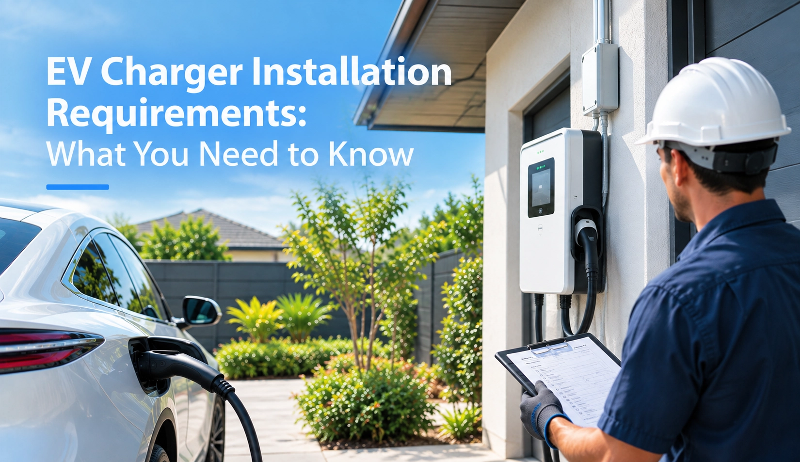
Safe, code-compliant EV charger installation requires evaluating electrical service capacity, installing dedicated branch circuits, obtaining local municipal permits, and choosing certified equipment. Residential Level 2 hardware runs on 208V–240V split-phase circuits (North America) or 230V/400V supplies (Europe), whereas commercial DC fast sites demand medium-voltage grid interconnections, dynamic load management, and strict compliance with NEC Article 625, UL 2594, IEC 61851, and IEC 60364-7-722.
1. Core Pre-Installation Requirements: Approvals, Property Rights, and Siting
2. Electrical Service Evaluation: Service Panels, Sizing, and Load Calculations
3. North American vs. European Technical Codes and Safety Standards
4. Physical Architecture: Hardwired vs. Plug-In, Conduit Runs, and Ingress Protection
5. Commercial, Multi-Family, and Fleet Infrastructure Requirements
6. Connectivity, Metering, and Dynamic Load Management (DLM)
7. Commissioning Protocols, Safety Testing, and Cost Expectations
Installing an electric vehicle supply equipment (EVSE) system involves infrastructure modifications. Skipping preliminary administrative checks often leads to project delays, code violations, or unexpected utility penalties.
Before sourcing hardware, installers and site planners must secure three operational baselines:
Jurisdictional Permitting and Landlord Clearances: In North America, municipalities require residential building and electrical permits before installation, followed by field inspections. In Europe, installation notices must be filed with local distribution system operators (DSOs) under regulations such as Germany’s NAV §19. Tenants in multi-unit dwellings must obtain approvals under regional "Right to Charge" legislation, which protects the tenant's right to install EV charging hardware at their own expense in assigned parking spaces.
Fixed Parking Stall Logistics: The vehicle parking spot must provide a safe path for the charging cable. The cable must not cross walking paths, sidewalks, or emergency egress routes. According to industrial standards, charging cables must measure between 20 and 25 feet (6 to 7.5 meters) to reach vehicle inlets regardless of how the vehicle is parked.
Civil Grounding and Structural Protection: Outdoor charging pedestals require concrete foundation pads, protective steel bollards to prevent vehicle impact, and grading to prevent pooling water around the unit during heavy rain.
FAQ: Can a tenant install an EV charger in a rented property?
Yes, if local "Right to Charge" statutes apply and the tenant pays for equipment, permitting, and licensed electrical labor. The property owner can specify conduit routing, cable management, and aesthetic standards to protect building integrity.
An electric vehicle charger functions as a continuous electrical load. In North America, the National Electrical Code defines a continuous load as any circuit draw sustained for three hours or more. Continuous loads cannot exceed 80% of the circuit breaker's maximum capacity.
To support a standard 32A to 48A residential Level 2 charging station, a certified electrician must complete a comprehensive load calculation to determine the spare capacity of the main panel.
| Continuous Output Amps | Dedicated Breaker Rating | Voltage & Phase Profile | Minimum Copper Conductor Gauge |
|---|---|---|---|
| 16 Amps (3.8 kW) | 20-Amp Dual Pole | 240V 1-Phase / 230V 1-Phase | 12 AWG (2.5 mm²) |
| 32 Amps (7.7 kW) | 40-Amp Dual Pole | 240V 1-Phase (NEMA 14-50) | 8 AWG (6.0 mm²) |
| 40 Amps (9.6 kW) | 50-Amp Dual Pole | 240V 1-Phase | 6 AWG (10.0 mm²) |
| 48 Amps (11.5 kW) | 60-Amp Dual Pole | 240V 1-Phase (Hardwire Only) | 6 AWG or 4 AWG (16.0 mm²) |
| 32 Amps 3-Phase (22 kW) | 40-Amp 4-Pole | 400V 3-Phase (European Standard) | 6.0 mm² – 10.0 mm² |
Homes built before 1980 often have 60-amp or 100-amp service panels that lack the physical space or thermal headroom for an added 40A to 60A circuit. While replacing the panel with a 200-amp service drops utility bills and expands capacity, automated load-shedding modules or circuit-sharing switches offer a cost-effective alternative. These devices monitor real-time household demand and pause vehicle charging when high-draw appliances like water heaters or air conditioning units run.
Electrical safety codes vary between European and North American installations due to differing grid structures. North American systems rely on 120V/240V split-phase power, whereas European infrastructure uses 230V single-phase and 400V three-phase distribution.
| Engineering Scope | North American Standards | European Standards |
|---|---|---|
| National Electrical Installation Code | NFPA 70: National Electrical Code (NEC Article 625) | IEC 60364-7-722 / BS 7671 (Section 722) |
| Equipment Safety Certification | UL 2594 (AC EVSE), UL 2202 (DCFC), CSA C22.2 | IEC 61851-1, IEC 61851-23, CE, ENEC |
| Residual Current & Ground Fault Protection | UL 2231-1 / UL 2231-2 (CCID 5mA / 20mA) | RCD Type B or Type A with RDC-DD (6mA DC detection) |
| Connector Topologies | SAE J1772 (Type 1), SAE J3400 (NACS), CCS1 | IEC 62196-2 (Type 2 Mennekes), CCS Charger (CCS2) |
A critical European requirement under IEC 60364-7-722 involves direct current leakage protection. Because vehicle rectifiers can leak smooth DC residual currents into AC supply lines, traditional Type A residual current devices (RCDs) can blind and fail to trip during ground faults. Installers must fit either a Type B RCD or a Type A RCD paired with an internal Residual Direct Current Detecting Device (RDC-DD) that trips if DC leakage exceeds 6 milliamperes.
Residential and commercial Level 2 hardware is deployed in two mechanical configurations: hardwired or plug-in.
Plug-in Installation (NEMA Receptacle): Plug-in units draw power through a four-prong receptacle (typically NEMA 14-50 or 6-50) on 240V circuits. This setup provides hardware mobility and simple equipment replacement. However, NEC Article 625 limits plug-in stations to 40 amps continuous output. Furthermore, NEC 2020/2023 requires GFCI protection on commercial and residential garage receptacles. Placing an external GFCI breaker upstream of an EVSE unit with built-in ground fault testing can cause nuisance tripping during power handshakes.
Hardwired Installation (Direct Conduit): Hardwiring connects the branch circuit directly to the charger's internal busbars using rigid or flexible metallic conduit. Hardwired connections support 48A to 80A outputs, reduce connection resistance points, eliminate redundant GFCI breaker tripping, and improve weather protection for outdoor installations.
For outdoor wallbox installations, weatherproofing standards are mandatory. North American installations require a minimum of NEMA 3R (rain/sleet resistant) or NEMA 4X (hose-directed water and corrosion protection). European installations require enclosures rated at least IP54 (splashing water and dust protected) or IP65 (dust-tight and water-jet protected), along with IK08 to IK10 mechanical impact ratings to protect the enclosure from physical strikes.
Commercial installations—including workplace parking lots, multi-family housing, logistics depots, and retail hubs—require electrical configurations beyond standard residential setups. Sites moving medium and heavy delivery vehicles rely on dedicated commercial DC Fast Charger hardware delivering 30 kW to 360 kW+, bypassing the vehicle's onboard converter entirely.
Deploying commercial charging infrastructure requires three core elements:
Dedicated Step-Down Transformers: DC fast chargers connect to 480V 3-phase circuits (North America) or 400V 3-phase circuits (Europe). Commercial sites must coordinate utility interconnection agreements to ensure local substations and distribution transformers can support the peak megawatt demand.
Accessibility Compliance: Public charging installations in North America must adhere to the Americans with Disabilities Act (ADA). Sites must provide dedicated van-accessible parking stalls, clear 36-inch transfer paths, and charger operating controls mounted between 15 and 48 inches above ground level. European installations follow EN 301 549 guidelines to maintain accessible physical heights and digital interfaces.
Underground Civil Trenching and Sub-Metering: Installing parking lot dispensers requires directional boring, sub-grade PVC conduit, reinforced concrete foundations, and revenue-grade utility sub-meters (such as MID-certified meters in Europe) to support billing across shared multi-family spaces.
Modern charging infrastructure relies on back-end connectivity to manage power delivery. Unmanaged charging stations can overload local service panels during peak evening hours, driving up commercial demand charges and risking substation outages.
To maintain balance, sites install smart chargers supporting Open Charge Point Protocol (OCPP 1.6J or 2.0.1) over hardwired Ethernet, secure Wi-Fi, or cellular telematics. This connectivity enables two key systems:
Dynamic Load Management (DLM): An on-site gateway measures total building power consumption in real time. If heavy building equipment cycles on, the system throttles charger amperage down across active stalls. Once facility demand drops, charging speeds automatically ramp back up, keeping total draw safely within utility limits.
Automated Time-of-Use (TOU) Dispatch: Smart chargers track utility rate tiers, scheduling sessions during low-cost overnight periods and enabling vehicle-to-grid (V2G) integrations under ISO 15118 protocols.
Completing physical wiring is only half the installation process. Before closing out permits, licensed electrical contractors must run functional tests using calibrated EVSE test adapters:
Ground Loop Impedance and Continuity: Verifying that the grounding conductor maintains low impedance to dissipate fault currents safely.
Control Pilot (CP) Simulation: Simulating vehicle states—State A (Disconnected), State B (Connected), State C (Charging), and State D (Charging with ventilation)—to confirm internal relays cycle correctly.
Trip Testing for Ground-Fault Protection: Injecting simulated AC and DC ground faults to verify the system trips within required millisecond safety windows.
| Installation Project Type | Hardware Cost Range | Permit & Electrical Labor | Potential Grid Upgrades |
|---|---|---|---|
| Basic Residential Level 2 (Adjacent to Panel) | $400 – $800 (€350 – €750) | $500 – $1,200 (€450 – €1,000) | $0 (Standard 200A service panel) |
| Complex Residential (Panel Upgrade / Trenching) | $500 – $1,000 (€450 – €900) | $1,500 – $3,500 (€1,300 – €3,000) | $2,000 – $4,500 (200A utility upgrade) |
| Commercial Dual Level 2 / Fleet AC Array | $2,500 – $6,000 (€2,200 – €5,500) | $3,000 – $8,000 (€2,800 – €7,500) | $2,000 – $10,000 (Subpanel & trenching) |
Installing EV charging equipment involves balancing electrical capacity, regional building codes, and future charging demands. Whether mounting a compact Level 2 wallbox in a home garage or commissioning a multi-megawatt depot, project success relies on completing upfront load calculations, selecting certified hardware, and adhering to regional safety standards.
By coordinating with certified electrical contractors, securing municipal permits, and incorporating dynamic load management, site owners can build safe, dependable charging infrastructure that lowers maintenance costs and supports reliable vehicle charging for years to come.
Technical references and regulatory standards cited in this installation guide: National Fire Protection Association (NFPA 70: National Electrical Code), International Electrotechnical Commission (IEC 61851 / IEC 60364-7-722 Standards), and US Department of Energy (AFDC) Charging Infrastructure Guidelines.